You are here:
MHV Feedthroughs>MHV floating shield
More options


MHV floating shield
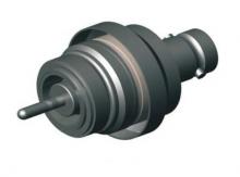
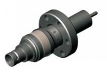
MHV floating shield single ended
MHV floating shield single ended
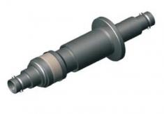
MHV floating shield double ended
| Type | Flange | N. pin | Conductor | Fig. | A | B | C | D | P/number |
|---|---|---|---|---|---|---|---|---|---|
| Single ended | Weld | 1 | 304 Stn. Stl | 1a see below | 17 | 27 | 2.38 | 32.63 | |
| Single ended | Weld | 1 | 304 Stn. Stl | 1b see below | 23 | 21 | 2.38 | 24.63 | 1-CX-0241 |
| Single ended | CF16 | 1 | 304 Stn. Stl | 2a see below | 51 | 32 | 2.38 | ||
| Single ended | CF40 | 1 | 304 Stn. Stl | 2b see below | 18 | 25 | 2.38 | ||
| Single ended | KF16 | 1 | 304 Stn. Stl | 3 see below | 66 | 17 | 2.38 | 1-CX-0148 | |
| Single ended | KF40 | 1 | 304 Stn. Stl | 3 see below | 53 | 30 | 2.38 | 1-CX-0149 | |
| Double ended | Weld | 1 | 304 Stn. Stl | 4a see below | 63 | 43 | 18.97 | 1-CX-0152 | |
| Double ended | CF16 | 1 | 304 Stn. Stl | 4b see below | 72 | 31 | 1-CX-0146 | ||
| Double ended | CF40 | 1 | 304 Stn. Stl | 4b see below | 64 | 42 | 1-CX-0147 | ||
| Double ended | KF16 | 1 | 304 Stn. Stl | 4c see below | 72 | 31 | 1-CX-0150 | ||
| Double ended | KF40 | 1 | 304 Stn. Stl | 4c see below | 63 | 43 | 1-CX-0151 |
| Voltage: | |
|---|---|
| Pin / shield: | 5000 VDC |
| Shield / ground: | 2500 VDC |
| Current: | 3 Amps |
| Impedence: | non constant |
| Material: | |
| Flange: | Stainless steel |
| Shell: | Stainless steel |
| Pin: | Stainless steel |
| Insulation: | Alumina ceramic |
| Vacuum range (UHV/HV): | 1x10⁻¹⁰ mbar / 1x10⁻⁸ mbar |
| Temperature range: | |
| CF & weldable FT: | -200°C to 450°C |
| Iso-K mounted FT: | -20°C to 150°C |
| Air sede connector: | -65°C to 165°C |
 Fig.1 - MHV floating single ended weldable drawings
Fig.2 - MHV floating single ended CF drawings
Fig.3 - MHV floating single ended ISO-K drawing
Fig.4 - MHV floating double ended drawings
 Air side connector included
In-vacuum connectors & cables available
Baseplate version available upon request
Custom configuration available upon request. Please contact our sales office.