You are here:
Ceramic breaks>Cryogenic breaks
More options


Cryogenic breaks
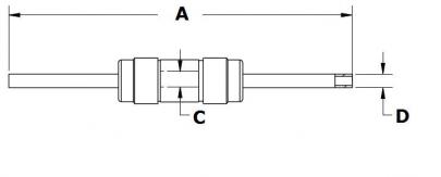
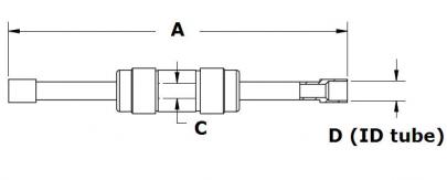
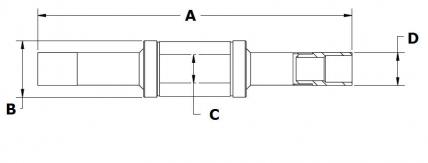
Fig.1
Fig.2
Fig.3
| Fig. | Voltage | A | B | C | D | P/number |
|---|---|---|---|---|---|---|
| 1 | 5 kV DC | 58 | 2.66 | 2.36 | 1-CC-0661 | |
| 1 | 5 kV DC | 46 | 2.66 | 3.17 | 1-BE-0850 | |
| 1 | 5 kV DC | 58 | 2.66 | 3.17 | 1-BE-0851 | |
| 1 | 5 kV DC | 43 | 2.66 | 2.36 | 1-BE-0852 | |
| 2 | 5 kV DC | 59 | 2.66 | 3.42 | 1-BE-0853 | |
| 3 | 10 kV DC | 76 | 14 | 6.85 | 7.87 | 1-BE-0883 |
| 3 | 10 kV DC | 76 | 14 | 6.85 | 6.35 | 1-BE-0854 |
| 3 | 10 kV DC | 76 | 20 | 10.92 | 11.17 | 1-BE-0855 |
| 3 | 10 kV DC | 76 | 20 | 10.92 | 9.65 | 1-BE-0856 |
| Voltage | up to 10kV DC |
|---|---|
| Material | Stainless steel |
| Insulation | Alumina ceramic |
| Temperature range | -200 to 450°C |
 Electrical breaks are often required in transmission lines for cryogenic fluid. Several standard designs are offered which are safe to operate to -200°C. These cryogenic breaks are intended to be TIG welded into cryogenic fluid transmission lines, and typical adapter designs are available with 3.2mm to 9.5mm diameters.